Cable Selection Guide for VFD Applications
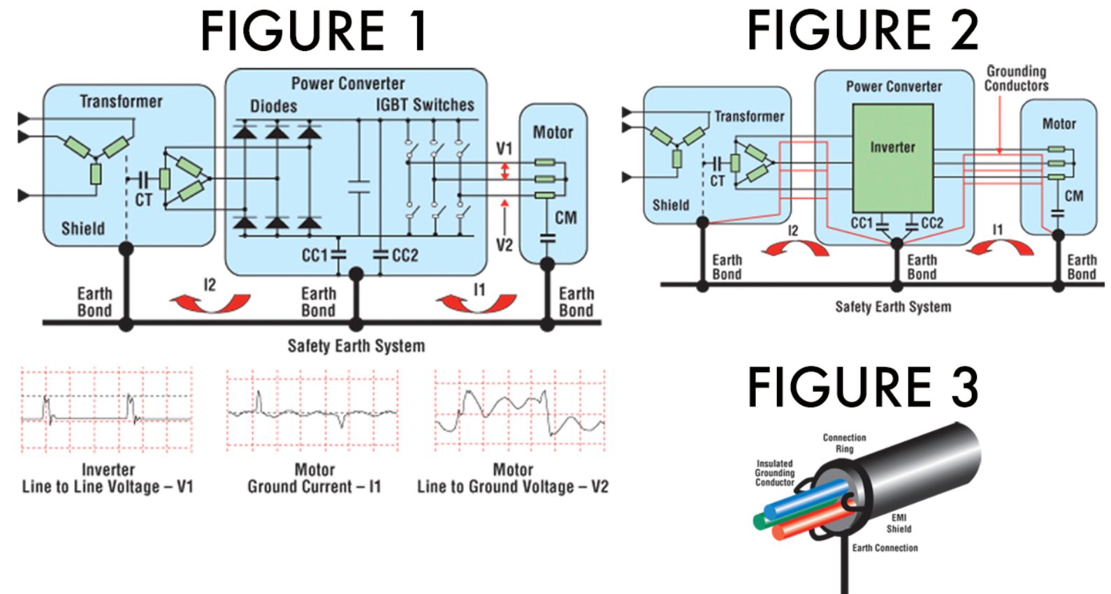
The circuit of a typical voltage source PWM drive is shown in Figure 1. Each part of the equipment is bonded to the safety earth system to ensure personnel safety if faults occur. All parts have capacitance to ground shown by:
- CM for the motor windings.
- CC1 and CC2 for the energy converter circuits
- CT for the transformer's secondary winding to the transformers' screen
The common mode voltages cause short high-frequency pulses of common mode current to flowin the safety earth circuits, shown by currents I1 and I2 Figure 1), unless the design includes cable features to stop this from happening. It is essential that the common mode currents return to the inverter without causing EMC - EMI problems in other equipment, and this means that the common mode currents I1 and I2 must not flow in the safety earthing system.
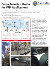
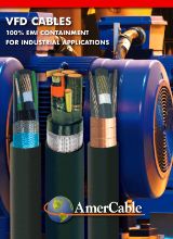
For the motor, this is achieved by connecting a set of wires from the motor to the inverter that run with the main energy cables. These are called symmetrical insulated grounding conductors, see Figure 2. These conductors have a very low impedance compared with the other return path via the safety earthing system. The three symmetrical insulated grounding conductors and overall shields are connected as shown in Figure 3. This 360 degree connectiohn is essential.
The common mode currents I1 and I2 now flow in the symmetrical insulated grounding conductors. This happens because the symmetrical insulated grounding conductors are close to the energy conductors giving a low impedance route for the currents I1 and I2 compared with the safety earthing system.
As I1 and I2 flow near the power conductors this avoids creating external EMC - EMI problems. If symmetrical insulated grounding conductors and an overall EMI shield are not used, EMC - EMI problems are very likely to occur.
For cables used with voltage source PWM drives, a number of features are required to ensure correct operation, avoid overheating and achieve longer service life.
The essential features of a medium voltage cable for PWM drives are:
- Insulation designed to withstand the transients produced by the PWM
- Insulation with a dielectric constant no greater than 3.0 to minimize capacitance
- Voltage rating of 3x the operating voltage to prevent corona
- Three symmetrical insulated grounding conductors. Some cables only have one grounding conductor. This is not acceptable as it produces circulating currents in the earth system
- Extremely fine strands to carry the harmonic currents without overheating (i.e. the inductance of fine stranded conductors is less than 7, 19, 37 strand conductors)
- Overall shield to stop the radiation of voltage EMI fields
- Correct termination at both ends
- Semi-conducting shield around each insulation layer
- Metallic layer around each semi-conducting shield to earth the semi-conducting shield
Learn More!
Our websites
Select your country to find our products and solutions
-
Africa
- Africa
- Ghana
- Ivory Coast
- Morocco
- North West Africa
- Americas
- Asia
- Europe
- Oceania